LCD display information
SPORTident Stations BS7/8/9
The onboard LCD display can provide a quick overview of the stations' settings and properties. The stations spend most of their life in standby mode. This is a low activity mode, which consumes very little power. In this mode, the LCD display is off. Switching from standby mode to active mode takes place when a SI-Card is inserted in the station. The maximum reaction time is 1 second. In active mode, the LCD display cyclically shows the function (including the control code) and the time. It will also display the SI-Card number during 3 seconds after it has been punched. This can be useful at the start to verify the number of the SI-Card of a runner.
From standby mode, the station can also be switched to service mode. This is done by inserting the Service/OFF instruction card into the station. In service mode the station shows additional information on the display and it is recommended to switch stations into service mode when the station should be configured with Config+.

indicates that the service mode is active. Service mode is automatically terminated after 5 minutes or when any kind of SI-Card is inserted into the station.
|
Operating mode CLR (CLEAR), CHK (CHECK), STA (START), FIN (FINISH), RDO (READOUT), CN (CONTROL), BST (Beacon Start), BFN (Beacon Finish), BCN (Beacon Control), ACN (SIAC Test), AC BT (SIAC Battery Test), AC ON (SIAC ON), AC OFF (SIAC OFF), AC RDO (SIAC Radio Readout). |
|
Time of day 24h format - HH:mm:ss |
|
OFF time The amount of minutes the station will be idling awake before automatically switching to standby mode. In this example, the unit will go to sleep 2 hours (120 minutes) after the last user punched the control. If the number is above 999, only the last 3 digits are displayed. |
|
Firmware The version of the software (firmware) installed on the station, in this case version 656. See section Config+ / Firmware update for the latest version. |
|
Station backup The number of punches that are currently stored in the backup memory of the station. |
|
Battery voltage The last measured battery voltage or BAT if no battery voltage has been measured. When it drops below 3.0V (BAT300), time is nearing for a battery replacement. |
|
Battery capacity Used capacity of the battery. A new battery will indicate CAP000. The example shows that the battery has consumed approximately 5% of its power. This value is a computed approximation, not the actual level. Accurate battery health check should be done depending on the battery voltage. |
|
Card full indicator The text FULLxy is shown in the display when the inserted SI-Cards memory is full and the punch cannot be written to the card anymore. An error entry will be written to the backup memory of the station. The station will not give any audible or visible feedback. |
|
Battery low indicator The tiny battery icon on the left side of the display is additionally displayed with the current information to indicate a low battery (battery voltage is below 3.0 Volts). So please make sure to replace the devices battery soon. |
SI-Stations BS11
The following information will cycle when the station is off but connected to USB charger
(available with firmware 700 and later only):
|
Device type Shows the device type of the station: BS11BL (Beacon large), BS11BS (Beacon small), BS11LA (Loop antenna) |
|
Serial number The serial number of the device |
|
Software version The software (firmware) version of the device. |
|
Battery voltage The battery voltage of the station: B + + + (voltage supplied by USB charger), B FULL (battery is fully charged) |
The following information will cycle on the display when the station is on. The displayed information differs slightly for the two main firmware versions:
Firmware 320 |
Firmware ≥ 700 |
Description |
|
|
CN xyz Control number of the SI-Station. |
|
← |
Time of day 24h format - HH:mm:ss |
|
← |
Operating mode
|
|
← |
Beacon mode PMODE (Punching mode), TMODE (Timing mode). |
|
← |
Gate mode Gate mode: |
|
|
Operating time Old notation: ON+599 (remaining operating time in minutes before the station will shut down), |
|
← |
Battery low indicator The tiny battery icon on the side of the display is additionally displayed with the current information to indicate a low battery. Depending on the display installation, this indicator can be either left or right side. The indicator is shown for a battery voltage below 3.5 Volts. So please make sure to recharge the devices battery soon. |
The following additional information will cycle on the display for the first minute only. The displayed information differs slightly for the two main firmware versions:
Firmware 320 |
Firmware ≥ 700 |
Description |
|
← |
Date The current date, either YYMMDD or YY.MM.DD |
|
|
Temperature Device temperature in degrees Celsius. |
|
|
Battery capacity The remaining battery capacity. |
|
|
Battery voltage The battery voltage of the device. If the display shows no voltage, please switch on the device without a USB charger connected, so it can measure the battery voltage. |
|
← |
Radio options Radio options for the SIAC |
|
← |
Serial number Unique serial number of the SI-Station. |
SI-GSM
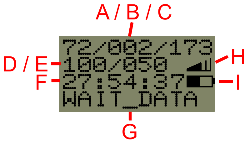
The following information will be shown on the display of a device prior to firmware 200: (Please find information for firmware ≥ 200 below)

A |
Number of ping (keep alive) signals sent to the server |
B |
Number of data records in the device buffer that still need to be sent to the server |
C |
Number of data records already sent to the server in this session. This value will overflow after 999 and start from 1 again |
D |
Internal state code of the device |
E |
Countdown timer in seconds until next ping (keep alive) signal is sent to the server |
F |
Toggles between current session time (HH:mm:ss) and ON 5759: remaining operating time in minutes until device switches off |
G |
Status text of the device. Most common texts are: |
H |
Graphical representation of the cell network signal strength |
I |
Graphical representation of the battery level |
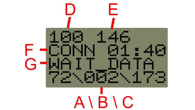
The following information will be shown on the display of a device with firmware 200 or later:

A |
Number of ping (keep alive) signals sent to the server |
B |
Number of data records in the device buffer that still need to be sent to the server |
C |
Number of data records already sent to the server in this session. This value will overflow after 999 and start from 1 again |
D |
Internal state code of the device |
E |
Countdown timer in seconds until next ping (keep alive) signal is sent to the server |
F |
Status information of the device: |
G |
Status text of the device. Most common texts are: |


